

YOUSAF S AL SULTHAN trading establishment (ENERGY DIVISION) is committed to give solution in the Energy Management System.
We are the sole distributor of the INDUSTRIAL CONTROLS & DRIVES(INDIA) PVT LTD products exclusively for the KINGDOM OF SAUDI ARABIA. The products are ISO 9001 certified products. We are the authorized Marketing,sales,installation, testing & commissioning and servicing of the ICDS controls in G.C.C.The Industrial controls products very much widely used in India in various fields such as HAL(Hindustan Aeronautical Limited-Govt of India undertaking), Aluminium Industries, Automobiles, Petro Chemical Industries, Cement Factories , Paper Mills, Steel Industries , Wind Mills, Power Plants , OEM, Tyre Industries , Commercial Complex – Malls, IT Parks , Textile Industries, Railways , Townships.
ICD has diversified its line of activities in the area of Energy Management Systems (EMS), Real Time Power Factor Correction Panels, Substation Automation Systems, Energy Saving Products viz, Thyristorized Heater Controllers, Lighting Energy Savers and Harmonic Filter Systems and custom designed systems.
With strong in-house technical expertise and Excellent customer / product support ICD has won the confidence and established rapport with the end users of Various Industries, Project Consultants, System Integrators, EPC Contractors, Panel builders and OEMs.
QUICK LINKS
Multi Function Meter
Data concentrator
Energy Billing System
Panel Meter
Ammeter
VAF Meter
Energen
Harmonic Filters
DC Energy Meter
Power Meter
Transducers
Multi Function Transducers
In Industries, commercial establishments, manufacturing plants etc. where the electrical system is huge and complex, it requires centralised monitoring of power, energy and control. ICD ENERGY MANAGEMENT SYSTEM is having such a facility and deals with "Demand side Management". The Energy Management System helps an organization to achieve energy efficiency through well laid out procedures and methods and in overall cost savings. This savings varies from savings in energy bills, maximum demand charges, controlling energy wastages, better utilization of man power and avoidance of critical break down in the electrical systems etc.
+ Do SWOT analysis of your plant energy with our EMS package to have awareness about the energy consumption, pattern of different production equipments, true energy cost for your different product. Energy cost allocation is made possible for various products and fix Energy saving formula. Evolve a typical Energy Cost Centre pattern. + Know your Plant Energy Efficiency, predict the Maximum Demand with your varying load profile and even out the varying demands to save Maximum Demand charges. + Improve your Plant Energy Efficiency by identifying the areas of wastage. Monitoring the trend of power factor, suitable power factor control scheme is made possible which not only avoids the penalty for poor factor, but also results in maximizing the incentive from EB. + Reduce Specific Energy Consumption for your Product by monitoring it on real time basis identifying the low productivity and wrong scheduling. + Even out the Demand and Energy will help you to achieve Optimum Utilization of your Transformers, Switch gears, Cables etc. + Know your potential for expansion or upgradation, thereby avoid unnecessary capital investment by analyzing the trend of all power parameters such as kW, kVA, kVAr, PF etc and knowing how close the operation is to the maximum ratings of the equipments. + Know the quality of your power and the pollution taking place with your loads using special meters (Harmonic Indicators-HAR 9000) at critical locations. + Assess your distribution losses accurately as a percentage of power transmitted and compare with the standards and bench marks to enable you to improve by suitable design / operational changes. + Since all the measuring devices are plus minus 0.5% accuracy and data acquisition is on real time basis, all the information are highly reliable. Hence right action can be taken without hesitation to achieve the desired results. + Compute energy bills yourselves, compare with that from EB and check your EB bills + Assured return on investment with low payback period and it is an investment and not an expense.
Automate Manage Schedule
This intelligent energy management software control system is designed to reduce energy consumption, improve the utilization of the system, increase reliability, predict electrical system performance, and optimize energy usage to reduce cost.
Automatic Generation Control Analysis
Automatic Generation Control (AGC) software calculates the required parameters or changes to optimize the operation of generation units. The automatic generation control software uses real-time data such as frequency, actual generation, tie-line load flows, and plant units’ controller status to provide generation changes.
• Multi-Area Automatic Generation Control
• Load Frequency Control
• NERC Performance Standard
• Generator Power Sharing (Real & Reactive)
• Minimize Area Control Error (ACE)
• Maintain frequency at the scheduled value
• Operate system with adequate security & economy
• Maintain net power interchanges
• Maintain economical power allocation
• Share MW and MVAR proportionally amongst various generation units
• Multiple pre-configured automatic generator control modes
Automatic generation control software is fully integrated with Economic Dispatch and Interchange Scheduling, automatically ensuring that generation adjustments are scheduled in the most economical fashion. AGC also calculates the parameters required for load frequency control and provides the required data on demand to maintain system frequency and power interchanges with neighboring systems at scheduled values.
Designed to minimize operating cost and improve life time of generation units
Monitors generation operating condition, running hours, maintenance schedules, etc. to determine which generators should be started\stopped to meet defined objectives.
The following objective can be achieved in EMS Commitment
• Minimize Fuel Cost (Efficiency)
• Minimize Current Running Hours
• Minimize Total Running Hours after Maintenance
• Minimize Total Running Hours after Installation
Interchange Scheduling Analysis
Interchange Scheduling (IS) provides the capability to schedule energy transfer from one control area to another while considering wheeling, scheduling ancillary services, and financial tracking of energy transactions. Dedicated for electricity power exchange and scheduling, Interchange Scheduling incorporates energy scheduling, transaction management, and energy cost analysis and reporting.
• Tariff Analyzer
• Rate Structure Builder
• Transaction Scheduling
• Transaction Contract
• Create detailed "Buy" & "Sell" transaction schedules
• Detailed energy transaction reports for user-specified period of time
• Evaluate energy cost per location (regions, areas, zones) for multiple transactions
• Extensive tariff builder
• Transaction management tools
• Energy cost analysis & reporting with user-definable formats
• Graphical & tabular energy cost & transaction views
Load Forecasting Analysis
Load Forecasting is an ideal tool for industrial users as well as utilities to reliably and accurately forecast future short term loading in the system.
• Adaptive Bus Load Forecasting
• Real-Time Trending
• Load Profile Library
• Forecasting Scenario Archiving
• Predict loading up to seven days ahead
• Forecast multiple load areas per individual meters
• User-adjustable weather variables & load profiles
• Revise forecasts based on loading & weather conditions
• Pattern & load profile libraries
• Import & export historical forecast data
• Unlimited forecast views
Reserve Management Analysis
Reliable operation of an isolated or interconnected power system requires adequate generating capacity to be available at all times while maintaining the scheduled frequency in order to avoid loss of firm loads following system contingencies.
• Operating Reserve Analysis
• Reserve Capacity Monitoring
• Predict Operating Reserve
• Notification of Inadequate Reserve
• Identify system-wide reserve capacity requirements
• Monitor & maintain regulating, contingency, interruptible imports, & on-demand reserves
• Easily replace generating capacity & energy lost due to forced outages
• Compensate for curtailment of interruptible imports from other areas
• Ensure reliable system operation
POWER MEASUREMENT PRODUCTS
Energy meters, Multi Function Meters, Load Managers and Trivector Meters can be selected depending on the customer requirement and application. Any third party meters with RS485 output supporting MODBUS RTU Protocol can also be used.
MEASURE & MANAGE POWER
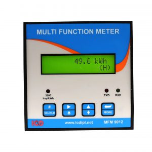
MULTI FUNCTION METER RATINGS
Voltage Inputs (Each channel) Full Scale Voltage : 300V AC L-N, 520V AC L-L Frequency Range : 30 - 70 Hz Starting Voltage : 25V AC L-N Burden : 0.2VA at 240V AC Current Inputs (Each channel) Full Scale Current : 6A AC Withstand Capability : 10A RMS Continuous, 100A RMS for 1 second Non-Recurring Starting Current : 0.2% of Full Scale Burden : 0.1VA at 5A AC Accuracy : Class 0.5, Class 0.2(Optional)
COMMUNICATION
Rs485 (Standard) : MODBUS-RTU Protocol, 2 Wire Connection up to 38400 Baud rate Ethernet (Optional) : MODBUS-TCP Protocol, RJ45 Jack, 10 / 100 Mbps self adaptable Profibus (Optional) : Profibus-DPV0 Slave protocol, 2 Wire connection, Baud rate adaptable up to 12 Mbps, Profibus standard according to EN50170
AUXILIARY SUPPLY
Operating Range : 90 - 270V AC, 50 / 60 Hz, 100 - 300V DC Burden : 4VA at 240V AC
I/O OPTION
Digital Input : 4 No's, 24V DC Self Excited Relay Output : 2 No's, 5A at 240V AC Digital Output : 2 No's Open Collector Transistor Output Pulse Output : 1 No, Pulse frequency 25 Hz, 50% duty Cycle Analog Input : 2 No's, 4 - 20mA / 0 - 1V, 0.2% OFS Accuracy, 1KV Isolation Analog Output : 1 No, 4 - 20mA, 0.5% OFS Accuracy, 1KV Isolation
OPERATING ENVIRONMENT
Operating Temperature : -10°C to +55°C Storage Temperature : -25°C to +75°C Relative Humidity : 5% to 95% non-condensing
CASE AND DIMENSIONS
Enclosure : Polycarbonate Dimension : 96 x 96 x 55 mm STANDARDS APPLICABLE Measurement Standard : IEC 62053-22, IS 14697 EMI / EMC standard : IEC 61000-4 / -2 -3 -4 -5 -6 -11, CISPR 22 Safety Standard : IEC 61010-1 Environmental Standard : IEC 60068-2 Outlines Standard : D
APPLICATIONS: Medium and Low Voltage Systems Panel Metering of distribution feeders, Generators, Transformers and Motors Power Quality Analysis and Data Logging Metering for Industries and utilities.
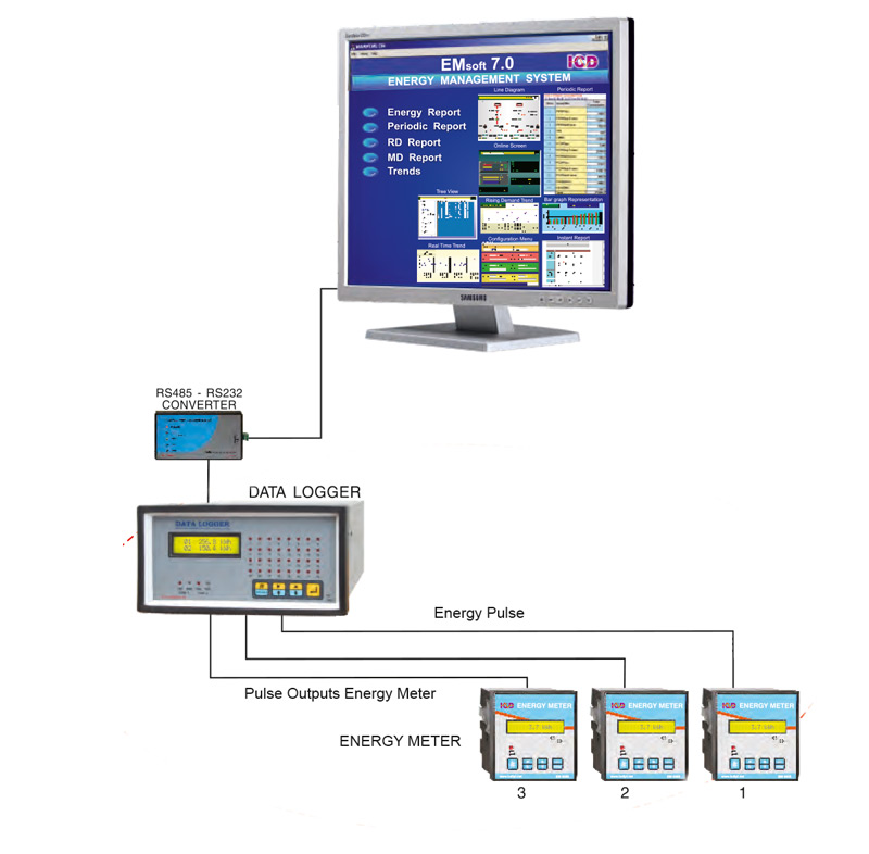
DATA LOGGER
Required for Interfacing with pulse output type meters. Each Data Logger has Provision to connect 60 / 30 meters.
DATA CONCENTRATOR
Required for interfacing meters with RS485 output. Each Data concentrator can support 30 individual meters. The Data Concentrators can be provided with RS485 output, Ethernet output or can be interfaced to a Fibre Optic Convertor, RF Modem and GSM/GPRS Modem. The use of Data Concentrators make the communication connections / grouping easier and also improves the speed of data collection.
MEDIA CONVERTORS
RS485 to RS232 Convertors, Repeaters, Fibre Optic Convertors, Ethernet Convertors, RF Modem and GSM / GPRS Modem depending upon the type of network used. The PROFIBUS Master Card (COMSOFT or HILSCHER make) is used in the PCI slot of the EMS Server PC for data collection through PROFIBUS network.
NETWORK CABLES
RS485 Cables, LAN Cables, Fibre Optic Cables and suitable other connection accessories
SOFTWARE PACKAGE
ICD EMSoft is totally indigenous Software Package designed for logging data from Data Concentrator, Data Logger and Individual Instruments.
The software package runs on Windows XP / Windows 2000 / Vista / Windows 7 and has all standard features for basic Energy Management. It has 4 Versions namely Micro, Compact, Professional, and Business with various different features to suit the customer requirements.
The software is capable to collect data through one or multiple com ports and through one or multiple ethernet ports EMsoft client software is an optional software used to view the datas in client PC connected in the LAN.
APPLICATION
Planning and Scheduling of Energy Resources
Energy Audit Applications and to create Management Information Report
Root Cause Analysis of Electrical Breakdown
Predictive Maintenance Helps in Achieving Energy Efficiency
Optimization of GenSet Running Hours
ENERGY BILLING SYSTEM (EBS)
FEATURES OF EBS
Data collection from meters are done through powerful Software package
User level security and privileges
Flexible and easy to configure meters and grouping of meters
EBS users and occupants configuration
Online data view in Tree structure
Daily, Periodical Trends and Reports
Alarm features for communications failure
Automated process for bill generation
Creation of bills from anytime to anytime on a click of a mouse button
APPLICATION
Most ideal for Energy Billing in Commercial Complexes, IT Parks, Residential Apartments and Industrial Housing Colonies etc.
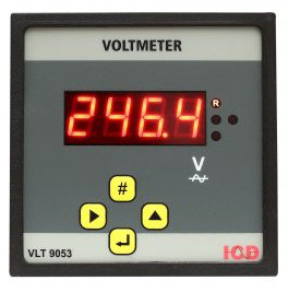
VLT 9053 True RMS measurement
3 Voltage readings in a single meter
4 Digit 0.5" 7 segment Red LED
Displays Phase & Line Voltages
R, Y, B, RY, YB, BR voltage display selection by push button
Phase indication by LEDs
Accuracy ±1% on reading
Accuracy ±0.5% on reading(Optional)
LT / HT Application Voltage Resolution (0.01KV for HT & 1V for LT)
Voltage input (110V AC for HT and 415V AC for LT)
PT Primary voltage selection through keypad
Auxiliary supply 90-270V AC/DC
96(H) x 96(W) x 45(D) mm 48(H) x 96(W) x 45(D) mm
Poly carbonate enclosure
Panel Mounting
Single Phase Volt Meter Model No. VLT 9051 available (Voltage range 300V AC) DC Volt Meter Model No. VLT 9059 available (Voltage range 10 - 300V DC)
AMM 9043 True RMS measurement
3 Current readings in a single meter
Accurate under Harmonic conditions
4 digit 0.5" 7 segment Red LED
Displays 3 Phase Current
R, Y, B display selection by push button
Phase indication by LEDs
Accuracy ±1% on reading +1 LSD
Accuracy ±0.5 % on reading +1 LSD (Optional)
Current Resolution (1A upto 1000A / 0.01KA above 1000A)
Current input 1A / 5A AC
CT Primary current selection through keypad
Auxiliary supply 90-270V AC/DC
96(H) x 96(W) x 45(D) mm 48(H) x 96(W) x 45(D) mm
Poly carbonate enclosure
Panel Mounting Single Phase Ammeter Model no. AMM 9041 available
DC Ammeter Input 75mV from DC shunt (Model no. AMM 9049) Input from External hall effect sensor (Model no. AMM 9049H)
CNF 240 4 Digit 0.5" 7 segment Red LED
Range 40.00 to 60.00Hz
Resolution 0.01Hz
Accuracy +0.05% on reading
Voltage Input 110V AC / 230V AC
Auxiliary supply 90-270V AC/DC
96(H) x 96(W) x 45(D) mm
48(H) x 96(W) x 45(D) mm
Poly carbonate enclosure
APPLICATIONS
Panel Metering in Sub Stations
Power Generation Plants,Genset Panels
Control Panels
Test Benches
Switch Boards
Power Distribution Panels
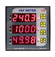
VAF 9000 Replaces Volt Meter, Ammeter and Frequency Indicator in an electrical panel
True RMS measurement LT / HT Application
12 digit 0.5" 7 segment red LED
Displays 12 parameters in a single instrument
Parameter displayed includes R, Y, B, RY, YB, BR voltage, R, Y, B current and frequency
Parameter selection through Front Panel Keypad
Phase indication and parameter indication through LED
Accuracy : ±1% on reading for voltage and current
±0.05% on reading for frequency
Resolution: Voltage 0.1V for LT, 0.01 KV for HT
Current 0.1A up to 100A, 1A (more than 100A) Frequency (0.01HZ)
Voltage Input: 100 - 520V AC line to line for LT 30 - 140V AC line to line for HT
Current Input: 5A / 1A AC
PT/CT setting through keypad with password facility
Auxiliary supply : 90 to 270V AC/DC
Dimension 96 x 96 x 45 mm
Poly Carbonate enclosure
Panel Mounting
APPLICATIONS
Panel Metering in Sub Stations
Power Generation Plants, Genset Panels
Control Panels
Test Benches
Switch Boards
Power Distribution Panels
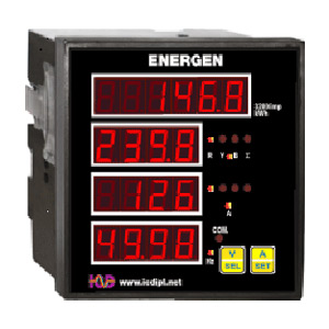
True RMS Measurement
LT / HT Application
18 Digit .39 inch 7 Segment LED
Confirms IS14697 for Accuracy Class 1 for energy
Direct reading without multiplication factor
Accurate on Harmonic Conditions
10 year back up for integrated energy data
Parameter displayed includes R, Y, B, RY, YB, BR voltage, R, Y, B current, frequency, kW or kVA, kWh or kVAh
Parameter selection through Front Panel Keypad
Phase indication and parameter indication through LED
Accuracy : ±1% on reading for voltage, current, kW or kVA
±0.05% on reading for frequency
Resolution: Voltage 0.1V for LT, 0.01 KV for HT
Current 0.1A up to 100A, 1A (more than 100A) Frequency (0.01HZ)
Voltage Input: 100 - 520V AC line to line for LT 30 - 140V AC line to line for HT
Current Input: 5A / 1A AC
PT/CT setting through keypad with password facility
Auxiliary supply : 90 to 270V AC/DC
Dimension 96 x 96 x 45 mm
Poly Carbonate enclosure
Panel Mounting
APPLICATIONS
Suitable for low cost applications
Captive Gensets
Individual Machines & Equipments
Pumps, Motors & compressors
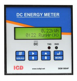
DEM 9004F
Parameter Shown : DC Voltage, DC Current, kW, kWh, Run hour
Voltage Range : 20 – 100V DC (One/Two Voltage channels)
Current Input : 50 mV / 75 mV from shunt (OR) 0 – 4 V from Split core Hall effect CT's
Four DC Current Channels
Current measurement through Shunt or Hall Sensors
Power Supply for Hall Sensors Provided in the meter
Programmable CT primary current individually for 4 channels
Displays DC Voltage, Current, kW, kWh and Run hour
Separate energy and run hour register provided for all the four channel
Digital Calibration by software
Energy & Run hour storage in EEPROM back up
kWh range 999999.99 kWh
Run hour range 9999.59 hours
APPLICATIONS
Telecom Tower Monitoring systems
Railway Power systems that uses DC supply
Solar Power System
DC Panel Meter, UPS
Any DC Plants that Needs Monitoring with PC Support
EM 9005
True RMS measurement
LT / HT Application
Suitable for single phase, 3 phase 4 wire, 3 phase 3 wire measurements
Confirms IS 14697 for accuracy class 1
Accuracy class 0.5 (Optional Confirms EMI / EMC standards (CISPR 14, IEC 61000 - 4 -1, IEC 61000 - 4 - 3, IEC 61000 - 4 - 4, IEC 61000 - 4 - 5)
Single row 16 character alpha numeric LCD with backlit
Displays kW, kWh, Run hour
kW / kWh selection through front panel key
Direct reading without multiplication factor
PT / CT setting through key pad
Low PT, CT burden (Less than 0.2 VA)
Energy storage in EERAM with 10 Years backup
Higher Meter constant 3200 Imp / kWh
Reverse Indication for proper connection
Measures 4 quadrant power and records import energy
Optically isolated open collector transistor pulse output for kWh
Wide range of Auxiliary supply (90 to 270V AC or DC)
Sealed dust proof Poly Carbonate Enclosure
Touch safe terminals
96(H) x 96(W) x 45(D) mm
Panel Mounting
Suitable for low cost applications
Captive Gensets
Individual Machines & Equipments
Pumps, Motors & compressors
Energy Data Logging using PLC/DCS
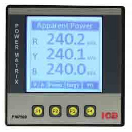
PWR 9070
True RMS Measurement
LT / HT Application
12 digit 0.5" 7 segment red LED
Displays all instant parameters in a single instrument
Direct reading without multiplication factor
Accurate on Harmonic Conditions
Accuracy class 1
Display parameter :kW, kVA, PF, kVAr 3 Phase Voltage, 3 Phase Current, Frequency, RPM, Power ON hours, Load ON hours and Number of interruptions
Low PT, CT burden (Less than 0.2 VA)
Digital Calibration ensures drift free operation for long time
High reliability and user friendly to configure and operate
Wide range of Auxiliary supply (90 to 270V AC or DC)
Sealed dust proof Poly Carbonate Enclosure
Touch safe terminals
96(H) x 96(W) x 45(D) mm
Panel Mounting
APPLICATIONS
Telecom Tower monitoring systems
Railway Power systems that uses DC supply
Solar Power System
DC Panel Meter, UPS
Any DC Plants that Needs Monitoring with PC Support
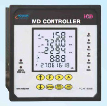
Better utilisation of available power
Avoid penalty, disconnection
Improved load factor
True RMS measurement
Auto scaling from KVA to MVA
Predictive control method adopted to optimise demand control
Field programmable CT &PT ratios
Time of the day(TOD) facility
Records 5 peak demands with date and time
Demand profile generation for setting realistic demand targets
3 control outputs for better control
Integration time selectable: 15/30 minutes
RS485 communication interface to PC (optional)
APPLICATIONS
Main incomers in substations
Hospitals and hotels
Process control industries
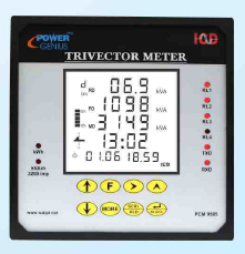
True RMS measurement
More than 75 parameters displayed in a single meter
3 or 2 element measurement
Accuracy class 0.5(IS14697)
Programmable PT/CT primary
Run hour indication
Replaces several meters in a electrical panel
Direct reading without multiplication factor
Selectable time base 15/30 minutes
Auto ranging of display parameters
Highly stable calibration by software means
Measures 4 quadrant
Low power consumption
Sealed dust proof ABS plastic enclosure
Low PT/CT burden (less than 0.2KVA)
Optically isolated RS485 communication output with MODBUS RTU protocol.
OPTIONAL FEATURES
Total harmonic distortion(THD) display of 3 phase voltage and current
RJ45 Ethernet connectivity with MODBUS/TCP support
Separate energy register for export energy recording
APPLICATIONS
Sub station metering
Industries and buildings
Hotels and Hospitals
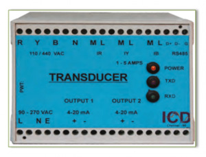
AC VOLTAGE TRANSDUCER
PWT 9060V
Measuring Quantity: AC Voltage
Nominal Input Voltage: 3/110V/240V/415V110V/
Measuring Range: (-40% to +20%)
Single (4-20mA) (0-10V) max.@ 20mA
Load Resistance 750
Accuracy class 0.5 as per IEC688
Ripple less than 1% (P-P)
Response time less than 500ms
Low voltage burden (less than 1VA)
Galvanic Isolation Provided (4kV)
Dual output option available
Self powered / External 48V DC / 110V DC 110V AC / 240V AC auxiliary
DIN Rail enclosure for easy onsite mounting
Dimension 70(H) x 55(W) x 110(D) mm
AC CURRENT TRANSDUCER
PWT 9060A
Measuring Quantity: AC Current
Nominal Input Current: 1A / 5A AC
Measuring Range: 0.2% to 120% of Ib
Single (4-20mA) (0-10V) max.@ 20mA
Load Resistance 750
Accuracy class 0.5 as per IEC688
Ripple less than 1% (P-P)
Response time less than 500ms
Low CT Burden (less than 0.2VA)
Galvanic Isolation Provided (4kV)
Dual output option available
Self powered / External 48V DC / 110V DC 110V AC / 240V AC auxiliary
DIN Rail enclosure for easy onsite mounting
Dimension 70(H) x 55(W) x 110(D)mm
FREQUENCY TRANSDUCER
PWT 9060F
Measuring Quantity: Frequency
3/110V/240V/415V
Nominal Input Voltage: 110V
Measuring Range: 45 to 55 Hz
Single (4-20mA) (0-10V) max.@ 20mA
Load Resistance 750
Accuracy class 0.5 as per IEC688
Ripple less than 1% (P-P)
Response time less than 1 second
Power consumption (less than 2VA)
Galvanic Isolation Provided (4kV)
Dual output option available
Self powered / External 48V DC / 110V DC 110V AC / 240V AC auxiliary
DIN Rail enclosure for easy onsite mounting
Dimension 70(H) x 55(W) x 110(D)mm
APPLICATIONS
Power Transmission and Generation Plants
Suitable to measure power system variable in high voltage / high current system
Remote Power Indicating Systems
Remote Large Size Display Systems
Data Logging using PLC / DCS
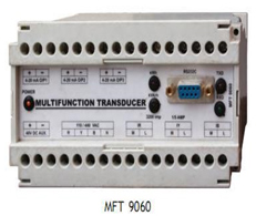
POWER TRANSDUCER
PWT 9060P
Nominal Input Voltage: 3/110V/415V/415V AC 3 Phase 110V
Nominal Input Current: 1A / 5A AC
Measuring Quantity: kW/kVAr/kVA/PF
Measuring Range: 0.2% I to 120% of I b b for kW/kVA/kVAr and 0.5 lag - 0.5 Lead for PF
Single (4-20mA) (0-10V) max.@ 20mA
Load Resistance 750
Accuracy class 0.5 as per IEC688
Ripple less than 1% (P-P)
Response time less than 500ms
Power consumption: 2VA
Galvanic Isolation Provided (4kV)
Dual output option available
Self powered / External 48V DC / 110V DC 110V AC / 240V AC auxiliary
DIN Rail enclosure for easy onsite mounting
Dimension 70(H) x 100(W) x 110(D)mm
MULTIFUNCTION TRANSDUCER
PWT 9060
5A / 1A AC Input
Overload 10 times Ib for 5 Seconds and 2 times Ib Continuous
Low CT burden. (Less than 0.2 VA)
Single 4-20 mA / Dual/Triple 4-20 mA output
Load Resistance 750 ohms maximum
Response time less than 500 ms
Galvanic Isolation Provided (4kV)
External 90 to 270V AC Auxiliary supply 75(H) x 150(W) x 110(D)mm
Din Rail Mounting
Programmable Features
Single phase, Three phase delta and 3 phase star measurement
Primary value of CT and PT
PT Secondary 415 / 110V AC
CT Secondary 1A / 5A
Programmable analog outputs (Voltage, Current, Frequency, kW, kVA, kVAr & PF)
Output can be configured for any of the measured variable
Specifications
Voltage Input : 25 - 520V AC L-L
Current Input : 5A / 1A AC
Over load : 10 times Ib for capability 5 seconds, 1.5 times Ib continuous
Starting current : 0.2% of basic current
Frequency range : 40.00 to 60.00Hz
Operating PF : 0.00 Lag to 0.00 Lead
Auxiliary supply : 48V DC / 90V - 270V AC/DC
Measured Variables : RMS voltage, RMS current, Active, Reactive, Apparent power (imp/exp) Power factor, frequency and energy
Communication : Optically isolated Rs485 communication supporting MODBUS RTU Protocol Rs232 Port is available for configuration menu driven windows
based software package is given at free of cost for configuration
Mounting : Din Rail / Wall Mounting
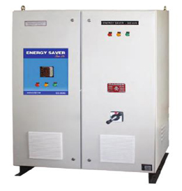
BENEFITS 10% - 20% direct energy savings on lighting loads
Reduced heat - hence cooler lamp operation
Reduced Air-conditioner cost - Because of cooler lamp operation
Increases the life of the lamp, hence reduced maintenance and replacement cost
Blackening of Florescent lamps and color shifting in metal halide lamps are reduced
Reduction in maximum demand due to reduced energy consumption Improves the power factor
Harmonics injected by electronic lighting ballasts to the line and spikes produced by lighting circuits are reduced, hence power quality is improved
Tax benefits available for energy saving investment
Pay back period is normally less than 12 month
Technical Specifications
Supply : Single Phase two wire Three Phase four wire
Voltage : 220 – 260V L-N for Single Phase 380 – 450V L-L for Three Phases
Rating : 5kVA – 100kVA for Single Phase 15kVA – 300kVA for Three Phases
Protection : Short circuit and overload protection through MCB/MCCB
Indication : a) R, Y, B power ON LED indication b) LED status indication for low, normal and high output voltage c) LED status indication for bypass and save mode
Power & Energy : ICD Multi Function Meter Monitoring Option
Mounting : Floor
APPLICATIONS
Campus Lighting in Large Industries and Commercial Establishments
Shopping Malls, Hotels, Hospitals, IT Parks and Commercial Complexes, Indoor and Outdoor Stadiums
Educational Institutions, Auditoriums
Campus Lighting in Public Sectors like Railways and Power generation plants
Textiles, Refineries and all major Process Industries
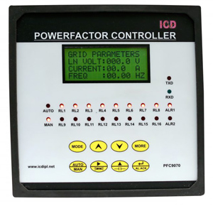
PFC 9059 / PFC 9059R
PFC 9059 - 6 Stage PF Controller with transistor output suitable for switching thyristors
PFC 9059R- 6 Stage PF Controller with relay output suitable for switching contactors
6-digit 0.34” seven segment red LED display
96(H) x 96(w) x 80(D) mm
PFC 9055 / PFC 9055R
PFC 9055 - 12 Stage PF Controller with transistor output suitable for switching thyristors
PFC 9055R - 12 Stage PF Controller with relay output suitable for switching contactors
7 digit 0.5” seven segment LED display
External potential free digital input provided to select EB/DG setting (optional)
RS-485 port for communication with MODBUS RTU protocol (optional)
PFC 9070/9070R (Enhanced Version)
PFC 9070 - 12 Stage PF Controller with transistor output suitable for switching thyristors
PFC 9070R - 12 Stage PF Controller with relay output suitable for switching contactors
Monitors both grid and panel parameters
4 row 16 character LCD display
Alarm against Over Voltage, Over Current, Over Compensation, Under Compensation & Step Fault
THD measurement and alarm (optional)
Disconnection of capacitor bank for excessive harmonics
Connection of permanent capacitor value in addition to the measured required power E.g. for compensation of a transformer
External potential free digital input provided to select EB/DG setting (optional) RS-485 port for communication with MODBUS RTU Protocol (optional)
DISPLAY OPTIONS
Grid Parameters
Voltage, Current, kW, kVA, kVAr, PF, Energy, Average Power Factor, Harmonics, Panel Parameters
Current, Capacitor kVAr, kVArh Pumped by the Alarm Status Alr1 – Critical Alarm Alr2 – Non-critical Alarm
Step History for each Step
Cycle count, Run Hour, Derating Percentage First value and Last value of Capacitor Bank
APPLICATIONS
Power Factor improvement in main incomers
Wind turbine generators
Hi-tech Software Parks, Buildings and Shopping Malls
Steel Rolling Mills and Process Industries
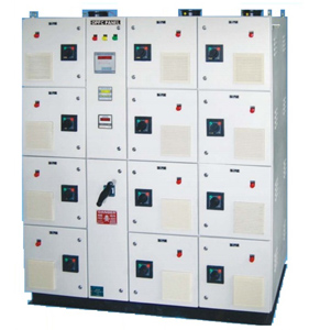
BENEFITS OF POWER FACTOR IMPROVEMENT
Substantial reduction in kVA demand and avoids penalty for low PF >
Considerable reduction of Transformer and line losses>
Reduction in voltage drop resulting in better system voltage regulation >
Reduction in maintenance, capital cost and longer life of distribution equipments due to lesser current carried in the system>
Reduction in voltage fluctuation and circuit reactance>
Reduction in reactive Power Demand from the supply system since PFC Panel compensates the reactive power of inductive loads >
Reduced I R losses >
Payback for the PF Panel is normally within 8 to 12 months>
Technical Specifications
System Voltage : 440V AC 3 Phase
Panel Rating : 50 kVAr to 800 kVA
Number of Steps : 4 / 6 / 8 / 12 / 16
Type of capacitor : Heavy Duty gas filled MPP/APP
Switching Device : Thyristor / Capacitor duty contactor
Panel Mounting : Indoor Application
Protection Class : IP42 Standard : IEC 60831
Panel Construction : Cubicle / Compartmentalized
APPLICATIONS
10 and 30 Welding Equipments
Wind Turbine Generators
Robotic Machinery Steel Rolling Mills
Elevators, Cranes, Presses
IT Companies, Hospitals
Water Treatment Plants
Air-conditioning etc.
HARMONICS
Any device with non-linear operating characteristics, draw current from the source which does not follow the voltage wave form and introduce wave form distortion in current. These wave form distortion in current are called current harmonics. The harmonic current produced by the non linear loads flow through the system impedances and generate voltage harmonics.
SOURCES OF HARMONICS
Variable Speed AC/DC Drives, UPS Systems, Rectifiers, SMPS, Static Converters, Thyristor controlled systems, Frequency controlled Induction furnaces, Arcing equipment, Arc furnaces, Welding, Lighting When saturation is reached in Transformers, Motors, Generators
PASSIVE HARMONIC FILTERS
When the harmonics present in the system is more, simple capacitor is not suitable for Power Factor improvement because, Capacitor reactance decrease with the increase of frequency. Hence it offers low impedance for Harmonic frequencies. So even smaller amplitudes of the harmonic voltages result in higher currents through the capacitors which are detrimental to the capacitors and power .
More critical is that the connected capacitors and the transformer inductance may cause a parallel resonant circuit. If this frequency matches the harmonic frequency, the resulting circuit amplifies the harmonics and lead to very high over voltage and over currents which is detrimental to the system.
Under these conditions de-tuned passive filter system of suitable tuning frequency is the solution for the improvement of Power Factor.
De-tuned capacitor banks consist of a series circuit of capacitor and a specific filter reactor. The resonance frequency of the de-tuned bank does not match close to any of the existing harmonic. It is normally lower than the lowest harmonic frequency present in the system, usually 5th harmonic.
De-tuned system ensures no resonant condition and no amplification of harmonic currents.
De-tuned system ensures a partial harmonic filtering effect reducing the level of harmonic voltage distortion on the supply.
TYPES OF PASSIVE HARMONIC FILTERS
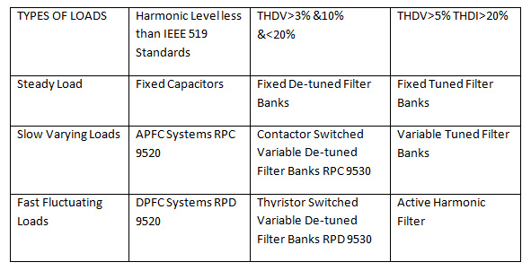
Contactor switched De-tuned Harmonic Filter System RPC 9530
Thyristor switched De-tuned Harmonic Filter System RPD 9530
Tuned Harmonic Filter System
BENEFITS OF HARMONIC FILTER SYSTEMS
Reduction of harmonic currents in the electrical network
Eliminates resonance condition, Improvement of True Power Factor
No de-rating of the transformers and motors due to harmonic losses
Better utilisation of the electrical system and system efficiency at its best
Good life expectancy for all the electrical and electronic components
Penalty by EB authorities for poor PF is avoided and hence reduced electricity bills
SELECTION GUIDE FOR PASSIVE HARMONIC FILTER SYSTEM
ACTIVE HARMONIC FILTER
Features
IGBT-PWM Voltage source converter technology with DSP based digital controller
Harmonic current cancellation better than IEEE519-1992 standards
Advanced control strategy to realize simultaneous cancellation of different harmonics
Programmable task priorities for power factor correction and harmonic cancellation
Response time less than 1 ms
Tested by CPRI, Bangalore, Proven technology from CDAC, Trivandrum
Rating 30 kVAr to 250 kVAr for 415/440V AC 3 Phase 4 wire
APPLICATIONS
Harmonic Filtering for AC / DC Motor Drives
Rectifiers used for battery charging applications
Welding Machines and Furnace applications
Power Factor improvement for all kind of loads in the presence of harmonics
Installation and Commissioning
ICD caters meter installation & commissioning services for Energy Management System which covers
Taking panel cutouts for new meters
Net working of meters using RS485 communication cable or RJ45 Ethernet CAT6 cable
Laying of Armoured or Unarmored cable
PT & CT wiring to meters
Laying of Fiber optic cable
Development, supply & installation of SCADA software package for Energy Management System
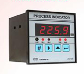
Microcontroller based design
Accurate and Reliable ON/OFF controller
Enhanced hardware compatibilities in compact enclosure
Accepts universal input and provides two relay outputs to perform various control and alarm functions.
0.5*7 segment Red LED displays for process value indication.
Front keys for easy programming
Process value can be re-transmitted to remote devices through current/voltage signals Transmitter power supply.
Suitable to work in Heat treatment furnaces, water heating boilers, chilers and oven control.
Accuracy class +/-0.5% OFS, optional +/-0.25%
96(H)x96(W)x80(D) mm
Optional RS485 communication output for Data Acquisition process on SCADA/PLC application
CERTIFICATES
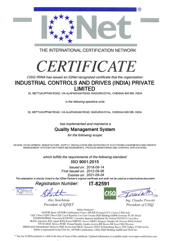
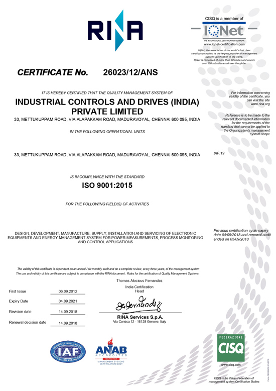
Our Product Types are Tested at
CPRI, Bangalore
ERDA, Baroda
Yadav Measurements Lab, Udaipur
Electronic Test & Development Centre, Chennai
Central Electrical Testing Laboratory, Thiruvallur